
|
|
1-LoopAntHome
2-Introduction
3-Characteristics
4-Comparisions
5-Data
7-Resources
|
|
6 - Construction Tips
|
Tubing Choices:
- Copper is the most practical choice (cost and good conductivity), though aluminum tubing will
also work.
- The main loop can even be coax (for low power). Hardline could be used for higher power levels.
- Use a larger diameter (> 1/2") copper tubing if you will be transmitting on your loop antenna.
- Trying to put larger amounts of power into a small tubing loop at higher frequencies will result in greater loop loss
(resistive impedance) due to the "skin effect".
- The "skin effect" becomes an increasing factor as the frequency goes up. At 1 MHz 63% of the current is within
.007 cm of the conductor surface; at 10 MHz most of the current is within .002 cm of the conductor surface
(that's 0.00079 of an inch).
- The resulting increase of Resistive Impedance (Rloop) will result in lower efficiency.
Loop Efficiency Formula
 . .
- Any power not radiated, but consumed by reistance, will show up as heating of the loop.
- Keep losses low and efficiency high by using the largest copper tubing possible.
Coupling Methods:
- A pick-up loop should be approximately 1/5th the size of the main loop.
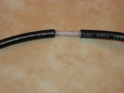
- Pick-up loops can be shielded or unshieled. Shielded pick-up loops must have a gap at the half-way point: cut the
insulation and shielding off to form a 3/4 inch gap (see attached pictures).
Make A Center Gap
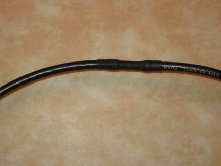
Center Gap with Shrink Tube Insulation
- The center conductor is then connected to the outer coax shield to complete the pick-up loop.
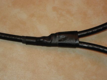
Center Conductor Termination
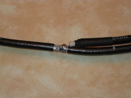
Center Conductor Termination
- Note that preparing a shielded loop in this manner supresses electrostatic noise and makes the entire antenna unresponsive
to nearby interference from electric fields.
- The pick-up loop coupling to the main loop may have to be adjusted to get the lowest SWR reading possible. Changing
the position of the pick-up loop or it's plane in relation to the main loop will effect the coupling and SWR.
- Gamma Match: formed with a conductor parallel to the main loop with a means of adjusting the second connection point.
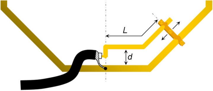 Gamma Match (from article by Leight Turner VK5KLT) Gamma Match (from article by Leight Turner VK5KLT)
- Torroid transformers can be formed by looping the antenna through a large toroid or winding wire around the loop tubing
for a pick-up. Remember to to use a toroid made from materials appropriate for the frequency involved.
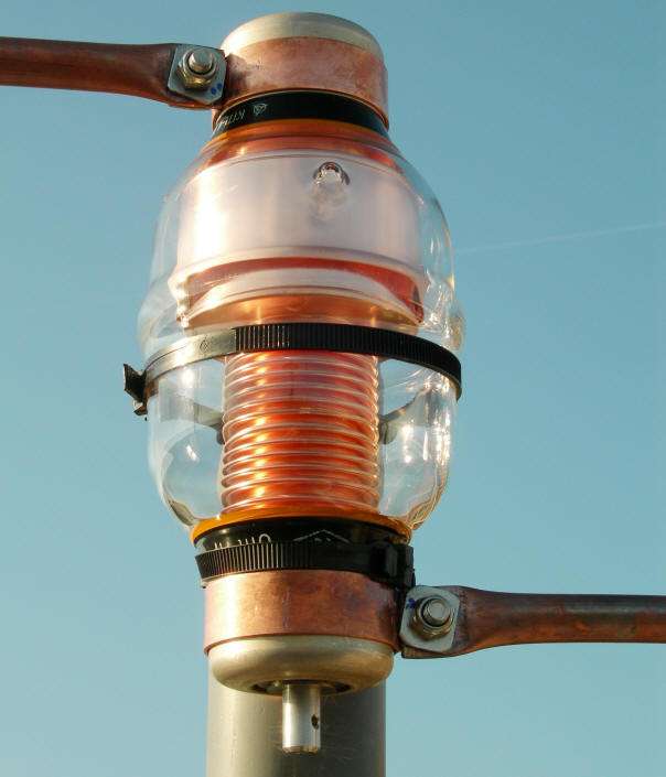
Capacitor considerations:
- Very high voltages (up to 10s of thousands of volts) can exist at the open loop ends.
- Standard wiper contact type variable capacitors should be avoided.
- High voltage split capacitors (butterfly) work well.
Two Gang Caps can be series connected to increase voltage rating
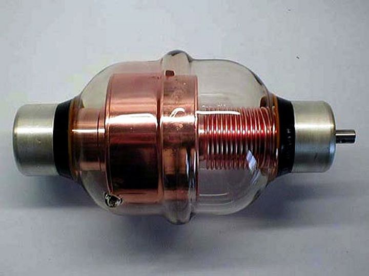
- Vacuum variable capacitors are very good (but very expensive).
- If you mount the tuning capacitor on the ground side of a loop antenna at a low height, ground losses
will occur similar to what would occur with a low mounted dipole. Does not apply in the desert!
- Need Remote Capacitor Tuning:
- Every time you change frequency by a few 10's of a kHz., retuning of the small loop antenna may be necessary.
- Some means of remote control of the tuning capacitor is required.
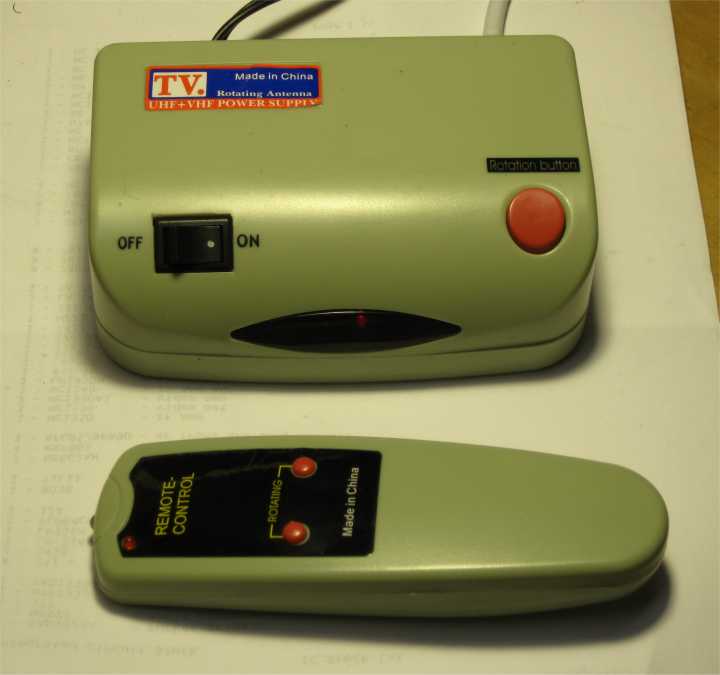
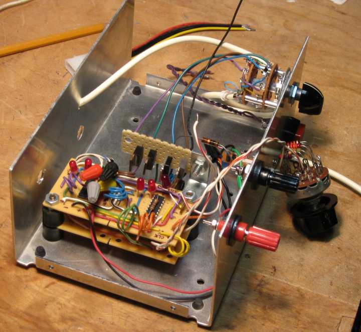
Inexpensive Tuning controller
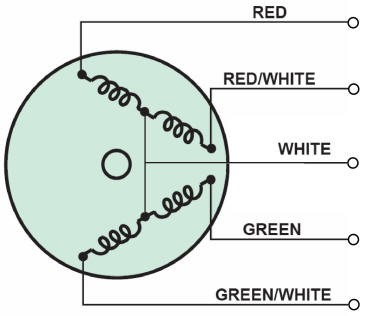
Stepping Motors Work Well For Tuning
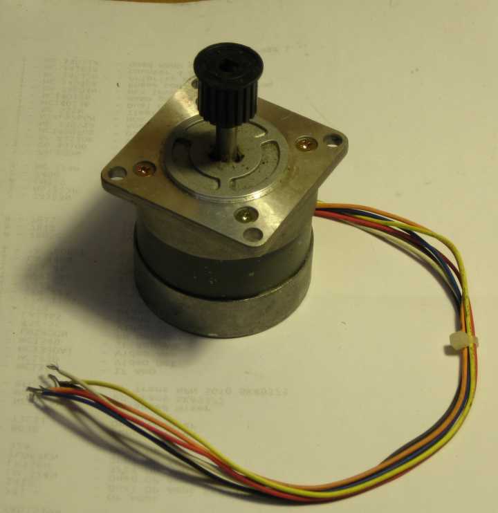
Step Motor Wiring (from article by Frank N4SPP)
- If the Q of your antenna is very sharp, which it is likely to be with this type of antenna, you will need some means of
fine tuning the action of the remote control on the variable capacitor.
Belt Drive (needs tension spring to work well
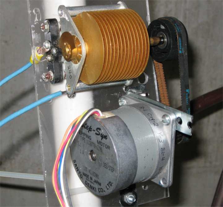 ) )
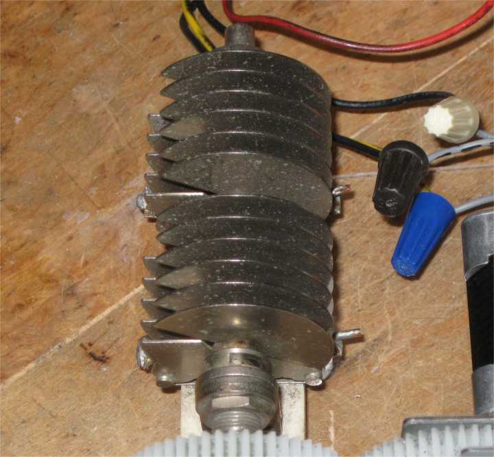
Gear Reduction works well
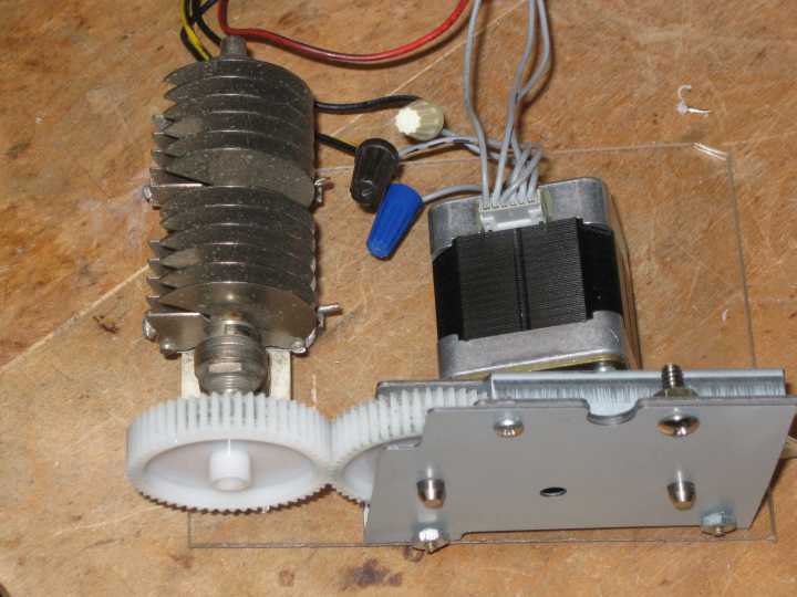
Fine Tune With Worm Gear
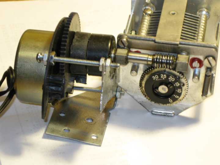
Stepping Motor Control - the way to go!
Construction methods:
- Good connections (soldered - not mechanical) are critical. If mechanical connections are necessary, they must
be sealed from the weather to prevent corrosive loop resistance which will drastically reduce the antenna efficiency.
Mechanical connections need sealing
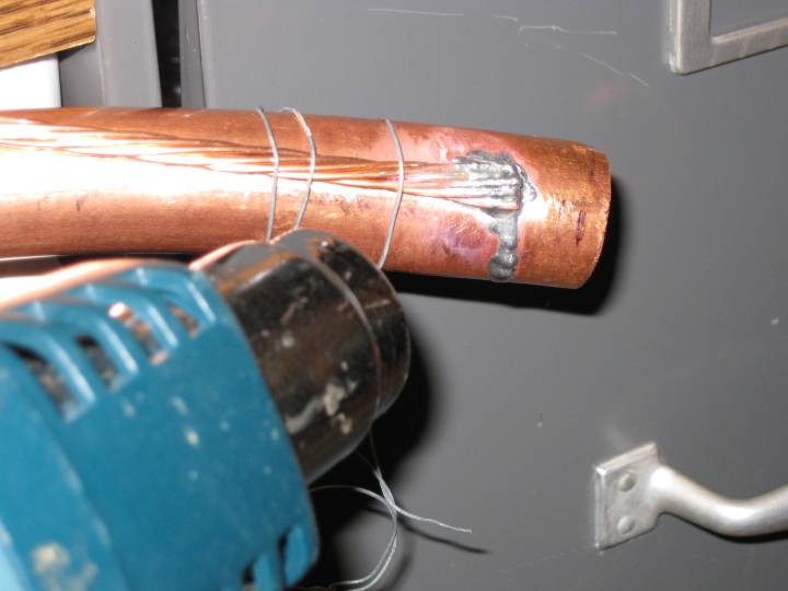
- Soldering large tubing may be challenging. Soldering irons will not work on larger tubing and pipe.
Soldering with heat gun
- Common Mode Choke is a necessity. Since the pick-up loop has the center coax conductor connected to the shield of the
coax, if you don't use a choke, common mode current will flow back down the outside of the transmission line and back
to the shack. This CMC will contribute to interference signals on other devices.
Mounting Consideration:
- Generally, a small loop antenna only needs to be mounted one diameter or more above normal ground.
- Nearby metal objects will couple to the magnetic field generated by the loop antenna and result in signal loss. If the
metal object is bigger than 1/3rd wavelength and less than 2 wavelengths away, it may create a serious null in that direction.
- Keep the loop antenna away from people (including yourself) to avoid exposure to the strong magnetic fields and high
voltages generated by this type of antenna.
Is Bigger Better?
- Yes! BIGGER IS BETTER!!!
- Using bigger tube sizes for your small loop has certain advantages.
- For a given circumference, a larger tubing size will result in a greater value of Q resulting in a "boost" in the received signals within a
tighter bandwidth and thus quieter reception.
- Bigger tubing also results in a greater antenna transmission efficiency due to lower loop resistive impedance loss (see the
previously noted "Efficiency Formula" and data below).
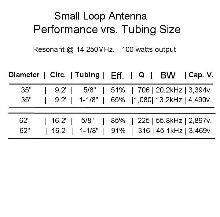
- While using larger tubing sizes for the main loop, note how the efficiency goes from 51% to 91% as the diameter approaches
the optimum 1/4 wavelength (at the 20 meter band frequency) and as the tubing size is increased from 5/8 inch to 1-1/8 inch.
BIGGER IS BETTER! (to a point)
Performance vrs. Tubing Size
- Bigger tube sizes for your small loop has certain disadvantages.
- Using very large tubing will result in a bandwith too narrow to be useable (the greater the Q the narrower the BW):
- Examples of Increasing Tubing Size @ 7.250 MHz and Constant Diameter:
- A 35 inch diameter loop of 5/8th inch tubing: Q = 931, BW = 7.79 kHz.
- A 35 inch diameter loop of 1-1/8 inch tubing: Q = 1,856, BW = 3.91 kHz.
- A 35 inch diameter loop of 4.0 inch tubing: Q of 6,405, BW of 1.13 kHz.
- A higher Q will also result in corresponding greater voltages across the tuning capacitor.
Voltages increase as Q becomes greater with larger tubing sizes.
- Example of Increasing Tubing Size with 100 watts @ 14.250 MHz. and Constant Diameter:
- A 62 inch diameter loop of 5/8 inch tubing: Q = 255, Capacitor Voltage = 2,897
- A 62 inch diameter loop of 1-1/8 inch tubing: Q = 316, Capacitor Voltage = 3,469
- At higher legal power levels these voltages can be well over 10,000 volts!
|
|
|
|